Interpretation of the schematic diagram of the electric solar container motor
Solar Combiner Box Wiring Diagram: Components and
How to wire a solar combiner box? Understand solar combiner box wiring diagram, its components, and installation best practices for efficiency
Schematic diagram of solar power water pump principle
When designing a solar pumping system,the designer must match the individual components together. A solar water pumping system consists of three major components: the solar array,pump controller and
The block diagram of solar electric vehicle
Solar modules and a Li-ion battery are used as energy sources, via MPPT; the output voltage is compatible for charging the battery and for supplying the

Solar-Powered DC Motor Control with ATS and AC
Explore comprehensive documentation for the Solar-Powered DC Motor Control with ATS and AC Backup project, including components, wiring, and code.
AC Motor Schematic Diagrams: Wiring Basics And Control For
AC motor schematic diagrams can represent various types of AC motors including synchronous motors and induction motors. Synchronous motors operate at a constant speed while
Wiring Diagrams for Electric Motors and Their Applications
Detailed wiring diagrams for electric motors, covering various types, configurations, and practical applications to simplify installation and troubleshooting.
Electrical schematic diagram of solar vehicle.
Download scientific diagram | Electrical schematic diagram of solar vehicle. from publication: Driving force characteristic and power consumption of 4.7 kW
Electrical Drawings, Schematics, and Wiring Diagrams:
The diagram will show the initial infeed and breaker, then distribute to many pages, each with categories of functions. Depending on the

Schematic diagram of the power generation system of
The detailed schematic diagram of the power generation system from the power container is also shown in Fig. 2 with relevant protective devices and switches of
How the solar motor works.
How the solar motor works. An electric motor transfers electrical energy into mechanical energy. The solar motor is a small direct current (dc) electric motor. Electricity flows through the motor in one

Circuit Diagram: How To Read And Understand Any
Learn to read and understand any circuit diagram. There are only a few things you need to know, then you can build whatever circuit you want.

A practical handbook for reading and analysing
Learn to to interpret drawings After reading and studying this handbook, electricians (or would-be electricians) will have a firm grasp on the
Designing a Powerful 48V 3KW Electric Vehicle
In this post I have explained a few important parameters related to the making of a 48V 3KW electric vehicle using solar panel, including a full
A Step-by-Step Guide: Wiring an Electric Motor
Learn how to wire an electric motor with a step-by-step diagram. Understand the different components and their connections for proper installation.
Electrical schematic diagram of energy storage system
A solar energy diagram helps installers avoid errors and ensure compliance with safety standards. single-line representation of the electrical components and their relationships within the
Schematic representation of the lift system using the
Download scientific diagram | Schematic representation of the lift system using the electric motor powered by solar energy from publication: COST ANALYSIS OF
Electric Motor Control Circuit Diagrams
Electric motor control circuit diagrams are a powerful tool to aid in this process, providing detailed instructions on how to safely and accurately

Reading a Solar Electrical Schematic
How to Read Electrical Diagrams | Wiring Diagrams Explained | Control Panel Wiring Diagram Blueprints Deciphered: How to Read Commercial Plans (For Electricians)
A Detailed Diagram of an Electric Motor: Understanding Its
Learn about the different parts and functions of an electric motor with a helpful diagram. Understand how electricity and magnetism work together to create motion.
Understanding Electrical Schematics: A Beginner''s Guide
This article will serve as a beginner''s guide to electrical schematics, covering the essential elements, common symbols, and steps to analyzing and interpreting

Schematic Diagram Fan Motor » Wiring Diagram
Schematic diagrams are an invaluable tool for understanding the inner workings of fan motors. For those unfamiliar with electrical engineering,

BESS Methodology
The power block of a DC-Coupled BESS schema is dependent on the electrical parameters of the PV plant primary inverters, the DC/DC converter characteristics and the battery containers.
Symbols And Schematic Diagrams Of Motor Control
This is achieved by using various electrical schematics and symbols to diagram a motor control system capable of providing the precision
Hydraulic and Electrical Diagrams of Empty Container
This document contains schematic diagrams and wiring diagrams for an empty container handler. The diagrams show the hydraulic, electrical, cooling, and
Schematic Interpretation
When considering the installation of solar panels on your home, schematic interpretation plays a crucial role in ensuring that the system is designed and installed correctly. A schematic diagram is a
Demystifying Electrical Diagrams and Schematics: A Beginner''s Guide
Learn how to read electrical diagrams and schematics to understand electrical systems and troubleshoot circuitry issues. Improve your electrical knowledge now.
A Beginner''s Guide to Reading Circuit Diagrams
Electrical schematics are essential for understanding and troubleshooting electrical systems. Whether you''re an electrician or an engineering student, learning to
Schematic of the common interpretation of the p-n
Download scientific diagram | Schematic of the common interpretation of the p-n junction solar-cell operation. from publication: Driving forces and charge-carrier
6 FAQs about [Interpretation of the schematic diagram of the electric solar container motor]
What are electrical schematics?Electrical schematics are essential tools for understanding and analyzing electrical circuits. These diagrams, also known as wiring diagrams or circuit diagrams, use symbols to represent electrical components and illustrate how they are connected and function within a circuit.
what-is-a-wiring-schematic?/">What is a wiring schematic?A wiring schematic is a diagram that represents the electrical connections between various components in a circuit or system. It is commonly used in the field of electrical engineering to document and understand the electrical layout of a device or installation. In a wiring schematic, different components are represented by specific symbols.
What is a motor wiring schematic?The electric motor wiring schematic typically includes symbols and labels to represent different components such as the motor windings, power supply, switches, capacitors, and other electrical devices. The connections between these components are shown with lines, indicating how the electricity flows through the motor.
What is solar-powered DC motor control with ATS and AC backup?Explore comprehensive documentation for the Solar-Powered DC Motor Control with ATS and AC Backup project, including components, wiring, and code. This circuit is designed to power and control a DC motor using energy from a solar panel, with an Automatic Transfer Switch (ATS) for AC grid backup.
Do you need a wiring schematic for an electric motor?When it comes to working with electric motors, having a clear and accurate wiring schematic is of utmost importance. A wiring schematic is a detailed diagram that shows the connections between various components of an electric motor system, including the motor itself, power supply, and control devices.
What are the symbols in an electrical schematic?In an electrical schematic, each symbol represents a different type of electrical device. These symbols can depict components like resistors, capacitors, switches, transformers, and more. The lines between the symbols represent the electrical connections between the components.
Related Contents
-
Schematic diagram of the deceleration solar container motor principle
-
Illustrated schematic of electric solar container motor principle
-
Schematic diagram of solar container peak load regulation and frequency regulation principle
-
Schematic diagram of home intelligent solar container system
-
Solar container station schematic diagram
-
Schematic diagram of solar container peak load regulation and reverse power transmission prevention
-
Schematic diagram of the principle of mechanical solar container device
-
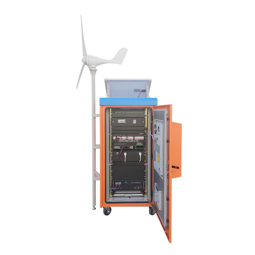
Schematic diagram of wind power generation and solar container
-
Schematic diagram of off-grid solar container battery principle
-
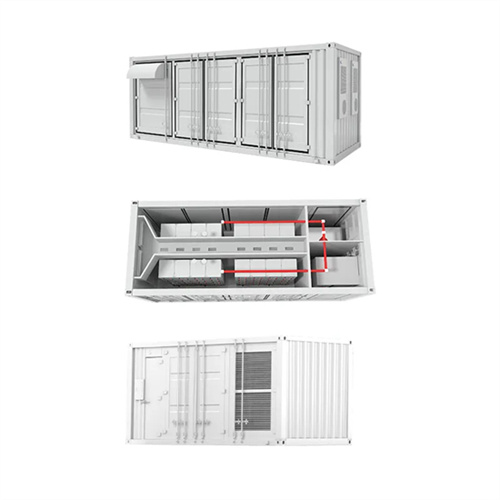
English schematic diagram of the complete design scheme of solar container power generation
-
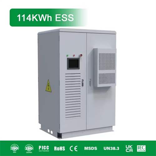
Schematic diagram of industrial solar container equipment
-
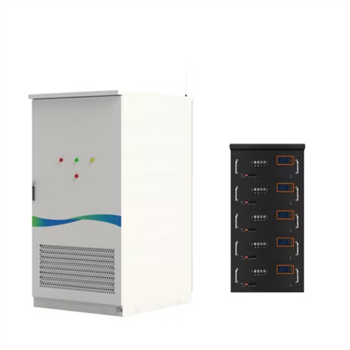
Solar container battery cluster high voltage box circuit schematic diagram
Get Your Free Solar Consultation Today!
Start saving with clean, renewable energy - request your custom quote now.
Electrical schematics are essential tools for understanding and analyzing electrical circuits. These diagrams, also known as wiring diagrams or circuit diagrams, use symbols to represent electrical components and illustrate how they are connected and function within a circuit.
what-is-a-wiring-schematic?/">What is a wiring schematic?A wiring schematic is a diagram that represents the electrical connections between various components in a circuit or system. It is commonly used in the field of electrical engineering to document and understand the electrical layout of a device or installation. In a wiring schematic, different components are represented by specific symbols.
What is a motor wiring schematic?The electric motor wiring schematic typically includes symbols and labels to represent different components such as the motor windings, power supply, switches, capacitors, and other electrical devices. The connections between these components are shown with lines, indicating how the electricity flows through the motor.
What is solar-powered DC motor control with ATS and AC backup?Explore comprehensive documentation for the Solar-Powered DC Motor Control with ATS and AC Backup project, including components, wiring, and code. This circuit is designed to power and control a DC motor using energy from a solar panel, with an Automatic Transfer Switch (ATS) for AC grid backup.
Do you need a wiring schematic for an electric motor?When it comes to working with electric motors, having a clear and accurate wiring schematic is of utmost importance. A wiring schematic is a detailed diagram that shows the connections between various components of an electric motor system, including the motor itself, power supply, and control devices.
What are the symbols in an electrical schematic?In an electrical schematic, each symbol represents a different type of electrical device. These symbols can depict components like resistors, capacitors, switches, transformers, and more. The lines between the symbols represent the electrical connections between the components.
Related Contents
-
Schematic diagram of the deceleration solar container motor principle
-
Illustrated schematic of electric solar container motor principle
-
Schematic diagram of solar container peak load regulation and frequency regulation principle
-
Schematic diagram of home intelligent solar container system
-
Solar container station schematic diagram
-
Schematic diagram of solar container peak load regulation and reverse power transmission prevention
-
Schematic diagram of the principle of mechanical solar container device
-
Schematic diagram of wind power generation and solar container
-
Schematic diagram of off-grid solar container battery principle
-
English schematic diagram of the complete design scheme of solar container power generation
-
Schematic diagram of industrial solar container equipment
-
Solar container battery cluster high voltage box circuit schematic diagram
Get Your Free Solar Consultation Today!
Start saving with clean, renewable energy - request your custom quote now.
A wiring schematic is a diagram that represents the electrical connections between various components in a circuit or system. It is commonly used in the field of electrical engineering to document and understand the electrical layout of a device or installation. In a wiring schematic, different components are represented by specific symbols.
What is a motor wiring schematic?The electric motor wiring schematic typically includes symbols and labels to represent different components such as the motor windings, power supply, switches, capacitors, and other electrical devices. The connections between these components are shown with lines, indicating how the electricity flows through the motor.
What is solar-powered DC motor control with ATS and AC backup?Explore comprehensive documentation for the Solar-Powered DC Motor Control with ATS and AC Backup project, including components, wiring, and code. This circuit is designed to power and control a DC motor using energy from a solar panel, with an Automatic Transfer Switch (ATS) for AC grid backup.
Do you need a wiring schematic for an electric motor?When it comes to working with electric motors, having a clear and accurate wiring schematic is of utmost importance. A wiring schematic is a detailed diagram that shows the connections between various components of an electric motor system, including the motor itself, power supply, and control devices.
What are the symbols in an electrical schematic?In an electrical schematic, each symbol represents a different type of electrical device. These symbols can depict components like resistors, capacitors, switches, transformers, and more. The lines between the symbols represent the electrical connections between the components.
Related Contents
-
Schematic diagram of the deceleration solar container motor principle
-
Illustrated schematic of electric solar container motor principle
-
Schematic diagram of solar container peak load regulation and frequency regulation principle
-
Schematic diagram of home intelligent solar container system
-
Solar container station schematic diagram
-
Schematic diagram of solar container peak load regulation and reverse power transmission prevention
-
Schematic diagram of the principle of mechanical solar container device
-
Schematic diagram of wind power generation and solar container
-
Schematic diagram of off-grid solar container battery principle
-
English schematic diagram of the complete design scheme of solar container power generation
-
Schematic diagram of industrial solar container equipment
-
Solar container battery cluster high voltage box circuit schematic diagram
Get Your Free Solar Consultation Today!
Start saving with clean, renewable energy - request your custom quote now.
The electric motor wiring schematic typically includes symbols and labels to represent different components such as the motor windings, power supply, switches, capacitors, and other electrical devices. The connections between these components are shown with lines, indicating how the electricity flows through the motor.
What is solar-powered DC motor control with ATS and AC backup?Explore comprehensive documentation for the Solar-Powered DC Motor Control with ATS and AC Backup project, including components, wiring, and code. This circuit is designed to power and control a DC motor using energy from a solar panel, with an Automatic Transfer Switch (ATS) for AC grid backup.
Do you need a wiring schematic for an electric motor?When it comes to working with electric motors, having a clear and accurate wiring schematic is of utmost importance. A wiring schematic is a detailed diagram that shows the connections between various components of an electric motor system, including the motor itself, power supply, and control devices.
What are the symbols in an electrical schematic?In an electrical schematic, each symbol represents a different type of electrical device. These symbols can depict components like resistors, capacitors, switches, transformers, and more. The lines between the symbols represent the electrical connections between the components.
Related Contents
-
Schematic diagram of the deceleration solar container motor principle
-
Illustrated schematic of electric solar container motor principle
-
Schematic diagram of solar container peak load regulation and frequency regulation principle
-
Schematic diagram of home intelligent solar container system
-
Solar container station schematic diagram
-
Schematic diagram of solar container peak load regulation and reverse power transmission prevention
-
Schematic diagram of the principle of mechanical solar container device
-
Schematic diagram of wind power generation and solar container
-
Schematic diagram of off-grid solar container battery principle
-
English schematic diagram of the complete design scheme of solar container power generation
-
Schematic diagram of industrial solar container equipment
-
Solar container battery cluster high voltage box circuit schematic diagram
Get Your Free Solar Consultation Today!
Start saving with clean, renewable energy - request your custom quote now.
Explore comprehensive documentation for the Solar-Powered DC Motor Control with ATS and AC Backup project, including components, wiring, and code. This circuit is designed to power and control a DC motor using energy from a solar panel, with an Automatic Transfer Switch (ATS) for AC grid backup.
Do you need a wiring schematic for an electric motor?When it comes to working with electric motors, having a clear and accurate wiring schematic is of utmost importance. A wiring schematic is a detailed diagram that shows the connections between various components of an electric motor system, including the motor itself, power supply, and control devices.
What are the symbols in an electrical schematic?In an electrical schematic, each symbol represents a different type of electrical device. These symbols can depict components like resistors, capacitors, switches, transformers, and more. The lines between the symbols represent the electrical connections between the components.
Related Contents
-
Schematic diagram of the deceleration solar container motor principle
-
Illustrated schematic of electric solar container motor principle
-
Schematic diagram of solar container peak load regulation and frequency regulation principle
-
Schematic diagram of home intelligent solar container system
-
Solar container station schematic diagram
-
Schematic diagram of solar container peak load regulation and reverse power transmission prevention
-
Schematic diagram of the principle of mechanical solar container device
-
Schematic diagram of wind power generation and solar container
-
Schematic diagram of off-grid solar container battery principle
-
English schematic diagram of the complete design scheme of solar container power generation
-
Schematic diagram of industrial solar container equipment
-
Solar container battery cluster high voltage box circuit schematic diagram
When it comes to working with electric motors, having a clear and accurate wiring schematic is of utmost importance. A wiring schematic is a detailed diagram that shows the connections between various components of an electric motor system, including the motor itself, power supply, and control devices.
What are the symbols in an electrical schematic?In an electrical schematic, each symbol represents a different type of electrical device. These symbols can depict components like resistors, capacitors, switches, transformers, and more. The lines between the symbols represent the electrical connections between the components.
Related Contents
-
Schematic diagram of the deceleration solar container motor principle
-
Illustrated schematic of electric solar container motor principle
-
Schematic diagram of solar container peak load regulation and frequency regulation principle
-
Schematic diagram of home intelligent solar container system
-
Solar container station schematic diagram
-
Schematic diagram of solar container peak load regulation and reverse power transmission prevention
-
Schematic diagram of the principle of mechanical solar container device
-
Schematic diagram of wind power generation and solar container
-
Schematic diagram of off-grid solar container battery principle
-
English schematic diagram of the complete design scheme of solar container power generation
-
Schematic diagram of industrial solar container equipment
-
Solar container battery cluster high voltage box circuit schematic diagram
In an electrical schematic, each symbol represents a different type of electrical device. These symbols can depict components like resistors, capacitors, switches, transformers, and more. The lines between the symbols represent the electrical connections between the components.
Get Your Free Solar Consultation Today!
Start saving with clean, renewable energy - request your custom quote now.