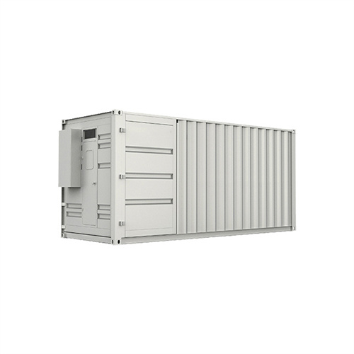
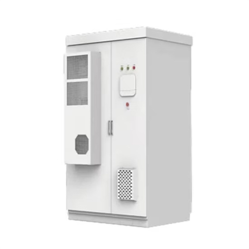
Voltage doubler solar container circuit

Voltage Multipliers: Doublers, Triplers, Quadruplers and
A half-wave voltage doubler is an electronic circuit that produces an output voltage approximately twice the peak value of the input AC voltage. It

Voltage Doubler and Multiplier – Making Easy Circuits
However the difficulty in full-wave voltage doubler is the fact that; in between the input and output we have to include a common ground line.
Highly efficient step-up dc–dc converter for photovoltaic micro
Abstract This paper presents a highly efficient step-up dc–dc converter for photovoltaic system. This converter is composed of an active resonant-clamp circuit and a resonant voltage

A revolutionary Partial Resonant Inverter and doubler rectifier with
This article presents a novel solar photovoltaic energy harvesting system for charging the high voltage Electric Vehicle (E.V.) battery using a Partial Resonant Inverter (PRI) driven doubler
Voltage Doubler: A Cheaper and Lighter Alternative to Transformer
Introduction to Voltage Doubler s A voltage doubler is an electronic circuit that converts an AC input voltage to a DC output voltage that is twice the peak input voltage. It is a type of voltage
Cockcroft-Walton voltage multipliers.
Here are some applications of the Cockroft-Walton voltage doubler circuit for generating high voltages from a low voltage AC source. The circuit is quite practical for generating thousands of volts (or more)

DIY Voltage Doubler & Multiplier – Easy Circuits for
Need a high voltage from low AC? Try these easy Voltage Doubler circuits – step-by-step guide with diagrams using just capacitors and

A Batteryless Inductive Energy Harvesting System
This study specifically addresses key design considerations such as coil design, resonance-matching, Schottky-diode-based rectifification, robust voltage regulation by means of a buck-boost converter
A DC-DC charge pump design based on voltage doublers
A two-phase voltage doubler and a multiphase voltage doubler (MPVD) structures are discussed and design considerations are presented. A simulator working in the – realm was used for simplified
Voltage Doubler for Solar Battery Charger circuit | Next Electronics
Not rated 23,141 #voltage doubler #solar #battery charger #energy #power supply #renewable energy #DC-DC converter #charging circuit Voltage Doubler for Solar Battery Charger
Resonant voltage doubler circuit for solar PV converter
In this paper a resonant voltage doubler circuit is reported on, which enables high efficiency and low power consumption of a solar cell DC-DC converter (PV converter) for solar cell
voltage doubler for solar panel | All About Circuits
I have two solar cells wired in series. I would like for someone to help me design a circuit to doubler the voltage or if not exactly double increase it by a margin. the ratings are 19.4 volts

7 Easy Voltage Doubler Circuits Discussed –
A voltage doubler circuit is also a form of voltage multiplier where the diode/capacitor stage is restricted to a couple of stages only, so that the

Full Wave Voltage Doubler Circuit
This electronics video tutorial explains the workings of the full wave voltage doubler circuit. This circuit converts an AC power source into a DC voltage w...
Voltage Doubler for Solar Battery Charger | REUK .uk
The Voltage Doubler Circuit Pictured above is the voltage doubler circuit diagram. It is made from some very cheap and easy to source components, the key
12V to 24V Voltage Doubler Circuit using IC 4093
This 12V to 24V Voltage Doubler Circuit can increase the operating voltage by as much as 200% and provides an output current capacity
Voltage Multiplier and Voltage Doubler Circuit
As its name suggests, a Voltage Doubler is a voltage multiplier circuit which has a voltage multiplication factor of two. The circuit consists of only two diodes, two

Voltage Doubler: A Cheaper and Lighter Alternative to Transformer
The voltage doubler circuit is an attractive alternative to traditional transformer- Rectifier Circuit s, as it offers several advantages, including lower cost, lighter weight, and reduced

7 Easy Voltage Doubler Circuits Discussed
In this article I have explained 7 easy to build DC to DC voltage doubler circuits using a single IC 4049 and IC 555 along with a few other passive components.
Simple Dc Voltage Doubler Circuit Diagram
Once assembled, the voltage doubler circuit will take an input voltage of around 1.5-9 volts and output a much higher voltage. This output can
A non‐isolated modified ultra high step‐up quadratic
The paper presented an improved version of high voltage gain DC–DC power electronics converter employing a voltage doubler circuit in the
Half-Wave & Full-Wave Voltage Doubler: Working &
The article provides an overview of half-wave and full-wave voltage doublers, explaining their working principles and circuit diagrams.

Voltage Doubler, Voltage Doubler Circuit,
A voltage doubler is an electronic circuit which charges capacitors from the input voltage and switches these charges in such a way that, in the
IC 555 Voltage Doubler Circuit – Making Easy Circuits
Voltage Tripler Circuit The circuit for the DC voltage quadrupler is depicted in the following figure and may produce output voltages between 20

Voltage doubler
OverviewVoltage doubling rectifiersSwitched capacitor circuitsBibliographyPrimary sources
A voltage doubler is an electronic circuit which charges capacitors from the input voltage and switches these charges in such a way that, in the ideal case, exactly twice the voltage is produced at the output as at its input. The simplest of these circuits is a form of rectifier which takes an AC voltage as input and outputs a doubled DC voltage. The switching elements are simple diodes and they are driven to switch state mer
6 FAQs about [Voltage doubler solar container circuit]
what-is-a-voltage-doubler?/">What is a voltage doubler?A voltage doubler is an electronic circuit which charges capacitors from the input voltage and switches these charges in such a way that, in the ideal case, exactly twice the voltage is produced at the output as at its input. The simplest of these circuits is a form of rectifier which takes an AC voltage as input and outputs a doubled DC voltage.
What is a step-up DC-DC converter for photovoltaic system?This paper presents a highly efficient step-up dc–dc converter for photovoltaic system. This converter is composed of an active resonant-clamp circuit and a resonant voltage doubler. The active resonant-clamp circuit limits the voltage stress and provides soft switching of the power switches.
how-does-a-doubler-work?/">How does a doubler work?In the series connection, the voltages add together. So, the output from the doubler is the applied voltage plus the voltage of C1. Current cannot flow through the rectifier D1 due to its one-sided conduction. The output waveform shows half-wave rectification with an amplitude of about twice the input voltage.
What is a voltage Tripler circuit?A “voltage tripler circuit” consists of one and a half voltage doubler stages. This voltage multiplier circuit gives a DC output equal to three times the peak voltage value (3Vp) of the sinusoidal input signal.
How many volts does a voltage doubler circuit produce?As soon as the circuit's output is loaded, the output voltage drops. Any DC source between 5 and 15 volts might operate with the voltage doubler circuit shown above. This can give voltage outputs across a range of roughly 10 to 30 volts due to its voltage doubling effect.
How many volts can a DC source run?Any DC source between 5 and 15 volts might operate with the voltage doubler circuit shown above. This can give voltage outputs across a range of roughly 10 to 30 volts due to its voltage doubling effect. Applying additional multiplier stages to the circuit will result in a higher voltage.
Related Contents
-
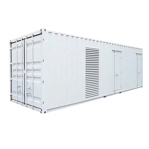
Short circuit voltage shows solar container
-
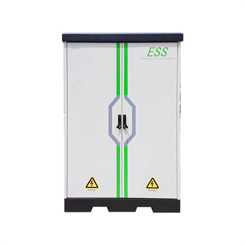
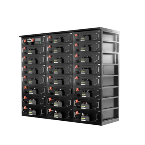
Solar container battery cluster high voltage box circuit schematic diagram
-
High voltage circuit breaker closed or open solar container
-
Abb low voltage circuit breaker replacement solar container assembly
-
Abb low voltage circuit breaker solar container mechanism diagram
-
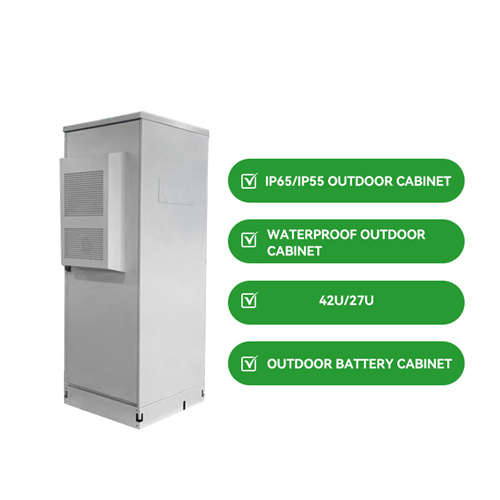
What is the voltage of the solar container battery pack
-
Solar container branch solar container circuit
-
Circuit breaker equipment solar container
-
Solar container battery voltage selection
-
Demonstration of the working principle of circuit breaker solar container device and complete design scheme
-
Video tutorial on the principle of pumped solar container circuit
-
Research on the current status of low voltage solar container industry development
Get Your Free Solar Consultation Today!
Start saving with clean, renewable energy - request your custom quote now.
A voltage doubler is an electronic circuit which charges capacitors from the input voltage and switches these charges in such a way that, in the ideal case, exactly twice the voltage is produced at the output as at its input. The simplest of these circuits is a form of rectifier which takes an AC voltage as input and outputs a doubled DC voltage.
What is a step-up DC-DC converter for photovoltaic system?This paper presents a highly efficient step-up dc–dc converter for photovoltaic system. This converter is composed of an active resonant-clamp circuit and a resonant voltage doubler. The active resonant-clamp circuit limits the voltage stress and provides soft switching of the power switches.
how-does-a-doubler-work?/">How does a doubler work?In the series connection, the voltages add together. So, the output from the doubler is the applied voltage plus the voltage of C1. Current cannot flow through the rectifier D1 due to its one-sided conduction. The output waveform shows half-wave rectification with an amplitude of about twice the input voltage.
What is a voltage Tripler circuit?A “voltage tripler circuit” consists of one and a half voltage doubler stages. This voltage multiplier circuit gives a DC output equal to three times the peak voltage value (3Vp) of the sinusoidal input signal.
How many volts does a voltage doubler circuit produce?As soon as the circuit's output is loaded, the output voltage drops. Any DC source between 5 and 15 volts might operate with the voltage doubler circuit shown above. This can give voltage outputs across a range of roughly 10 to 30 volts due to its voltage doubling effect.
How many volts can a DC source run?Any DC source between 5 and 15 volts might operate with the voltage doubler circuit shown above. This can give voltage outputs across a range of roughly 10 to 30 volts due to its voltage doubling effect. Applying additional multiplier stages to the circuit will result in a higher voltage.
Related Contents
-
Short circuit voltage shows solar container
-
Solar container battery cluster high voltage box circuit schematic diagram
-
High voltage circuit breaker closed or open solar container
-
Abb low voltage circuit breaker replacement solar container assembly
-
Abb low voltage circuit breaker solar container mechanism diagram
-
What is the voltage of the solar container battery pack
-
Solar container branch solar container circuit
-
Circuit breaker equipment solar container
-
Solar container battery voltage selection
-
Demonstration of the working principle of circuit breaker solar container device and complete design scheme
-
Video tutorial on the principle of pumped solar container circuit
-
Research on the current status of low voltage solar container industry development
Get Your Free Solar Consultation Today!
Start saving with clean, renewable energy - request your custom quote now.
This paper presents a highly efficient step-up dc–dc converter for photovoltaic system. This converter is composed of an active resonant-clamp circuit and a resonant voltage doubler. The active resonant-clamp circuit limits the voltage stress and provides soft switching of the power switches.
how-does-a-doubler-work?/">How does a doubler work?In the series connection, the voltages add together. So, the output from the doubler is the applied voltage plus the voltage of C1. Current cannot flow through the rectifier D1 due to its one-sided conduction. The output waveform shows half-wave rectification with an amplitude of about twice the input voltage.
What is a voltage Tripler circuit?A “voltage tripler circuit” consists of one and a half voltage doubler stages. This voltage multiplier circuit gives a DC output equal to three times the peak voltage value (3Vp) of the sinusoidal input signal.
How many volts does a voltage doubler circuit produce?As soon as the circuit's output is loaded, the output voltage drops. Any DC source between 5 and 15 volts might operate with the voltage doubler circuit shown above. This can give voltage outputs across a range of roughly 10 to 30 volts due to its voltage doubling effect.
How many volts can a DC source run?Any DC source between 5 and 15 volts might operate with the voltage doubler circuit shown above. This can give voltage outputs across a range of roughly 10 to 30 volts due to its voltage doubling effect. Applying additional multiplier stages to the circuit will result in a higher voltage.
Related Contents
-
Short circuit voltage shows solar container
-
Solar container battery cluster high voltage box circuit schematic diagram
-
High voltage circuit breaker closed or open solar container
-
Abb low voltage circuit breaker replacement solar container assembly
-
Abb low voltage circuit breaker solar container mechanism diagram
-
What is the voltage of the solar container battery pack
-
Solar container branch solar container circuit
-
Circuit breaker equipment solar container
-
Solar container battery voltage selection
-
Demonstration of the working principle of circuit breaker solar container device and complete design scheme
-
Video tutorial on the principle of pumped solar container circuit
-
Research on the current status of low voltage solar container industry development
Get Your Free Solar Consultation Today!
Start saving with clean, renewable energy - request your custom quote now.
In the series connection, the voltages add together. So, the output from the doubler is the applied voltage plus the voltage of C1. Current cannot flow through the rectifier D1 due to its one-sided conduction. The output waveform shows half-wave rectification with an amplitude of about twice the input voltage.
What is a voltage Tripler circuit?A “voltage tripler circuit” consists of one and a half voltage doubler stages. This voltage multiplier circuit gives a DC output equal to three times the peak voltage value (3Vp) of the sinusoidal input signal.
How many volts does a voltage doubler circuit produce?As soon as the circuit's output is loaded, the output voltage drops. Any DC source between 5 and 15 volts might operate with the voltage doubler circuit shown above. This can give voltage outputs across a range of roughly 10 to 30 volts due to its voltage doubling effect.
How many volts can a DC source run?Any DC source between 5 and 15 volts might operate with the voltage doubler circuit shown above. This can give voltage outputs across a range of roughly 10 to 30 volts due to its voltage doubling effect. Applying additional multiplier stages to the circuit will result in a higher voltage.
Related Contents
-
Short circuit voltage shows solar container
-
Solar container battery cluster high voltage box circuit schematic diagram
-
High voltage circuit breaker closed or open solar container
-
Abb low voltage circuit breaker replacement solar container assembly
-
Abb low voltage circuit breaker solar container mechanism diagram
-
What is the voltage of the solar container battery pack
-
Solar container branch solar container circuit
-
Circuit breaker equipment solar container
-
Solar container battery voltage selection
-
Demonstration of the working principle of circuit breaker solar container device and complete design scheme
-
Video tutorial on the principle of pumped solar container circuit
-
Research on the current status of low voltage solar container industry development
Get Your Free Solar Consultation Today!
Start saving with clean, renewable energy - request your custom quote now.
A “voltage tripler circuit” consists of one and a half voltage doubler stages. This voltage multiplier circuit gives a DC output equal to three times the peak voltage value (3Vp) of the sinusoidal input signal.
How many volts does a voltage doubler circuit produce?As soon as the circuit's output is loaded, the output voltage drops. Any DC source between 5 and 15 volts might operate with the voltage doubler circuit shown above. This can give voltage outputs across a range of roughly 10 to 30 volts due to its voltage doubling effect.
How many volts can a DC source run?Any DC source between 5 and 15 volts might operate with the voltage doubler circuit shown above. This can give voltage outputs across a range of roughly 10 to 30 volts due to its voltage doubling effect. Applying additional multiplier stages to the circuit will result in a higher voltage.
Related Contents
-
Short circuit voltage shows solar container
-
Solar container battery cluster high voltage box circuit schematic diagram
-
High voltage circuit breaker closed or open solar container
-
Abb low voltage circuit breaker replacement solar container assembly
-
Abb low voltage circuit breaker solar container mechanism diagram
-
What is the voltage of the solar container battery pack
-
Solar container branch solar container circuit
-
Circuit breaker equipment solar container
-
Solar container battery voltage selection
-
Demonstration of the working principle of circuit breaker solar container device and complete design scheme
-
Video tutorial on the principle of pumped solar container circuit
-
Research on the current status of low voltage solar container industry development
As soon as the circuit's output is loaded, the output voltage drops. Any DC source between 5 and 15 volts might operate with the voltage doubler circuit shown above. This can give voltage outputs across a range of roughly 10 to 30 volts due to its voltage doubling effect.
How many volts can a DC source run?Any DC source between 5 and 15 volts might operate with the voltage doubler circuit shown above. This can give voltage outputs across a range of roughly 10 to 30 volts due to its voltage doubling effect. Applying additional multiplier stages to the circuit will result in a higher voltage.
Related Contents
-
Short circuit voltage shows solar container
-
Solar container battery cluster high voltage box circuit schematic diagram
-
High voltage circuit breaker closed or open solar container
-
Abb low voltage circuit breaker replacement solar container assembly
-
Abb low voltage circuit breaker solar container mechanism diagram
-
What is the voltage of the solar container battery pack
-
Solar container branch solar container circuit
-
Circuit breaker equipment solar container
-
Solar container battery voltage selection
-
Demonstration of the working principle of circuit breaker solar container device and complete design scheme
-
Video tutorial on the principle of pumped solar container circuit
-
Research on the current status of low voltage solar container industry development
Any DC source between 5 and 15 volts might operate with the voltage doubler circuit shown above. This can give voltage outputs across a range of roughly 10 to 30 volts due to its voltage doubling effect. Applying additional multiplier stages to the circuit will result in a higher voltage.
Get Your Free Solar Consultation Today!
Start saving with clean, renewable energy - request your custom quote now.